The drive shaft felt OK when I bought the vehicle but with 170,000 miles on it, it would be better to take it apart and put some new U joints in it.
They actually still looked good, the grease was hard and black, there was some brinelling from the needles but it would have lasted a few more years. The rubber donut looked fine, so I just re-used it. You can still buy new ones, they are used by BMW on some of their older models.
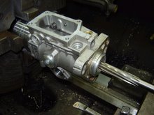
I bought some new universal joints for it at Lordco, they are not listed under Vanagon Syncro but under PTO shafts, size is 27 mm x 70 mm. Before I paid for them, I checked with a small file if they were heat treated, a lot of u joints are soft and won't last at all. They came with a grease nipple and 2 circlip sizes so you can take the play out of them.
I had to machine the grease nipples so that they would screw in deeper, they won't fit as supplied.
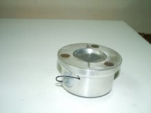
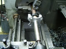
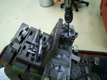
An often overlooked problem with the later style Syncro drive shafts are the bronze bushings that are located under the rubber donut, they wear out and cause vibrations in the drive line.To remove them, I put a thread into them, 1'' just fits, then used a piece of ready rod with nut, washers and a piece of pipe to pull them out.
Mine had a lot of wear and corrosion and I had to machine 0.035" off the shaft to clean it up, I made two new bronze bushings and pressed them back in the drive shaft. Next I fitted it all back together, I had to use the thicker circlips in order to get all the play out of the cups.
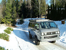
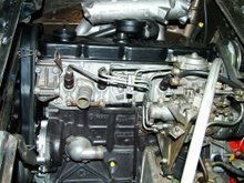
On the Syncro, it is important that the drive shaft is well aligned, both the tranny and the front diff flanges have an angle of about 4 degrees. If you do an engine conversion, and the engine hangs too low, you could end up with some vibration. Another thing to watch out for when doing a conversion is that the original VW engine is slightly offset towards the driverside, about 17 mm, if the new engine is installed in the center of the engine compartment, it will put another angle on the drive shaft that is not compensated for by the front diff and it may cause a vibration also. It is too bad that VW didn't put a CV joint in, one would have been enough.
On a two wheel drive Vanagon it is not that critical if the engine is centered, the axle CV joints will compensate for that.
Total cost for the U joints was about $ 80.00 and it took me 5 hours to machine the parts and put it all back together.
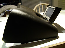
Roof overhang
Pull it towards you to get the pin out
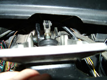
Pedal frame

Installed
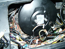
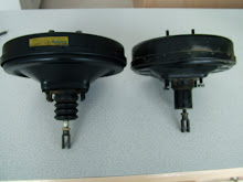
BMW booster is on the left
Closed

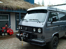
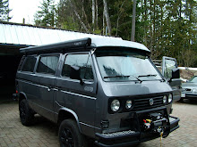
New paint job


Modified synchro


Rear Bumper


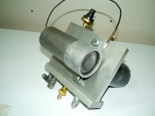
Eberspacher BN2 Heater

Aux fuel transfer pump

Valves just fit in the 76 mm bore

Tool to hold piston for machining

Piston

Making Hydrogen

Shock will slide in tube

Cut the eyes off

Front shock extenders

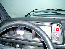
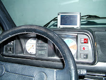
Gauge pod


Extra retaining washer


Laser alignment tool

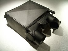
Intercooler
New universal joint
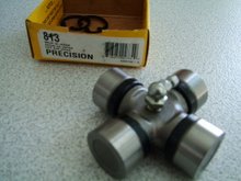
Part number is on box
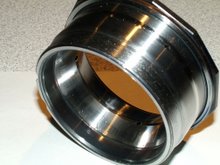
New bushings
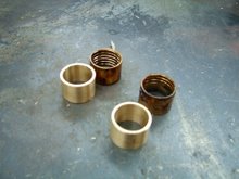
Undersized bushings
Drive shaft
Cleaned up surface
Drive shaft
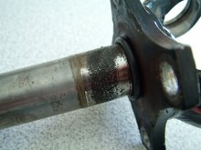
Corrosion
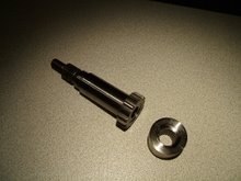
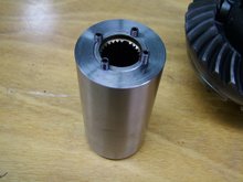
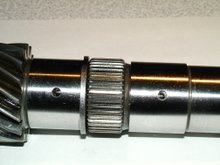
Decoupler shaft and gear hub
gear hub before cutting of teeth
Coupler before torquing set screws
Machined differential housing
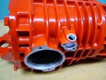
Locking front differential
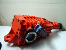
Locking front differential

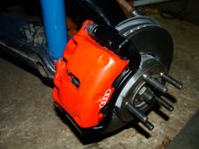
Audi A4 or Jetta VR6 rear calipers

Rear disc brakes
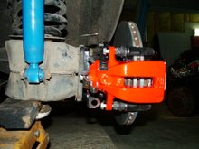
Audi 5000 Turbo brakes

Oil holes drilled
Pinion bearing race
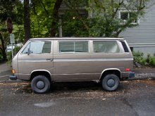
How it started
Audi 2.0 TD engine

Drilling and reaming vac pump
Test fitting the engine
Prelube pump
You can see one of the two filters
Injection pump
Reaming the bushing to size
Home made 2.5" stainless muffler.

Audi logo
24 comments:
hi there. you say you engineered your own decoupler, i am search of engendering drawings,
Hi,I never made any drawings of it but I basically copied the original output shaft and put on external teeth that matched the internal teeth of the Chev S10 front diff slider.
Then I made a hub with the same external teeth and machined internal splines on it so that it would fit the transmission shaft.
Next came a shift fork and shaft that would fit the housing.
This is not easy to machine if you don't have access to a milling machine, lathe and shaper.
It is way easier to make the other type, just machine a bronze collar that slides onto the original Syncro coupling sleeve and is held in place by 2 snaprings and make a small fork and rod to shift it in and out.
Great work.
hi,
did you have any trouble pressing the vw u joints out? and was is tricky to get the new ones in?
I've heard that that can be fussy
Alistair
Hi Alistair, pressing them out was not hard, I took the circlips and shims out and cleaned the bore with sand paper, put a bit of grease in it and it came right out.
Putting them back in is a little harder, press one cup in a bit deeper, put the opposite cup in so that the needles just catch on the stub.Then press the cups into position. The cups have to be centered with the shims, it is a bit finicky but not hard to do.
Cheers Herman
Thanks Herman, working on U joints this afternoon. Will disassemble, grease, and re-install the old ones as practice.
Working on my new van, '86 syncro pass van. At same time I got the van I also got an old (1980?) Lantain 10x24 lathe. Always have wanted a lathe, and the price was right on this one. I have much to learn. My first project i the repair of a sway bar drop link. Broke just at the shoulder of narrow section. The link is not straight, has a slight bend in it so it was a little fiddly to get it mounted on four jaw chuck so I could face end and drill hole to tap for replacement "stud". But that part worked out well. Next step is to turn a stud and thread both ends. (you realise its a practise exercise as well). I'll weld the stud once its screwed in.
cheers
alistair
another few questions...
the bronze? bushings... how did you determine they were worn? was there obvious looseness in the joint?
and the stock you used to make new ones, bronze or some "bushing material"?
and what stops the bushings from moving in the housing? just the press fit?
and... did you ream or use a boring bar to fit them.
these must seem pretty elementary questions.
thanks,
alistair
HI Alistair, when you take the rubber donut off and put the shaft back into the bore, I noticed quite a bit of play, which will cause a vibration in the drive shaft.
I have used bronze for the bushings as that was what the original bushings were made of.
I machined both bushings on the lathe with the same outside diameter as the old ones and a slightly smaller internal diameter.
Then I pressed them back into the bore and machined the shaft on the lathe for the right clearance, about 0.0015" or so.
Cheers, Herman
Thanks for the explanation Herman.
I didn't feel any looseness in the assembly. Also the shaft looked pretty smooth and clean with the exception of a little bit of bronze colour on the outboard bearing surface. And there was plenty of greasy grease.
I'm going to take the chance and keep the old bushings.
I replaced the u-joints with the same "Precision #813" units you used. One cup out of the 8 went in easily, I was a bit concerned but the joints seem pretty secure.
I did not need to shim nor use the thicker circlips.
I have a blurry pic of the old u-joints here:
http://rangnarhairybreeks.blogspot.com/
look at that bearing! that was from the end opposite the doughnut.
cheers,
alistair
hi,
been working off and on, more off than on I guess, at tacking down prop shaft vibrations at around 60 kph. I have replaced u joints and checked fit of bushings and guibo. I also made a laser alignment jig similar to yours and using that (and confirming with my little Beall Angle box electronic angle finder) I determined that the front diff flange is "pointing down" at about 2.5 degrees, and the transmission flange is pointing down at about 4.5 degrees.
I'd like to have the angles the same, and preferably under 4 degrees. The front diff has some up and down freedom via the 2 bolts on the yoke type hanger, but it seems to be at the limit of downward travel as is. And i'd prefer not to match the 4.5 degrees of the transmission. So back to the tranny, and I really dont see how I can move it on the front mounts. the nose needs to go up a tad, but that looks like it means reducing the "thickness" of mount between the trans mount ear and the plate bolted to the van body.
I do have to admit that I haven't tried pushing up on tranny nose to see if it is actually hanging loose and low. woll be doing that today.
but aside from that, any advice?
thanks
alistair
Hey Alistair, you could add some spacers between the engine mount bracket on each side where it is bolted to the frame, that will bring the tranny flange up a bit.
Are you sure that the bracket that you have in there is from a Syncro?
There is a difference between the regular one and the Syncro one. 4.5degrees is quite a bit.
Cheers Herman
Hi,
well, no I am not sure engine carrier is a syncro one. will go out and check. I don't have full vehicle history, someone could mucked things up in the past :)
I had a chance to try more things (and to refine my laser jig). I looked more closely at tilting the front diff to match the transmision angle. I discovered front mount of front diff did not have the plastic spacers installed that the other mounts have. Further, the underside rubber mount had deformed in comparison to the upper (pics on my blog, http://shufti.wordpress.com/). Ekta does not show spacers there, but does list them on the side in a confusing manner. Also other syncro owners I talked to have the spacers there. Its not clear what is going on. Anyway, I swapped the rubber mounts, upper to lower and put in a few washers to raise front of front diff. I did not accurately measure angle change, I can't recall numbers except it was around 1/2 degree diff, flange vs flange., I did test drive with rubber mount bolts loose, vibrations still there, in a narrow band around 50 kph.
I think I will have time this weekend to do accurate measurements and deal with any lateral misalignment.
thanks for your help,
cheers
alistair
yup, proper engine carrier, no mistaking it :)
Do you have the plastic spacers on the front diff front mount?
alistair
I remeasured flange angles, came out pretty close to what i did casually before, 3.7 degrees on front diff, 4.6 on trans. Pics here
http://shufti.wordpress.com/2010/06/20/better-measurements-of-flange-angles/
alistair
Hey Allister, sorry for the delay, I have been away for a few weeks.
I thought you were talking about a flat nylon spacer but after looking at your website you show the plastic bottom half of the transmission mount, this is standard on all front differential and transmission mounts and should be in place.
Your laser alignment tool looks great!
Cheers Herman
Herman,
well its thanks to you I made that laser pointer, but I couldn't get it accurate the same way you did :)
As to the plastic spacers on the trans and diff mounts... I don't think the front mount on front diff had one in my van. I checked hole diameter in mount and tried a spacer, wouldn't fit. Maybe there was a change in some year? Can you make absolutely sure you have one on that front mount, I'm very curious.
Seems my prop shaft vibes may be due to unbalanced shaft, I posted info on my blog
http://shufti.wordpress.com/
cheers
alistair
Hi Alistair, you are right, the front mount doesn't have the plastic spacers, just the two rear mounts have them, I just checked on both of my Syncro's, no plastic spacers on the front center mount.
Cheers Herman
Herman,
did you pull the inner bushing out of the tube with the propshaft still fully intact?
alistair
Hi Alistair, yes you can pull it out of the tube with the drive shaft intact. The inside diameter will become slightly smaller after you press it in, so you may have to machine the male part down a bit in a lathe to make it fit correctly.
Cheers Herman
Herman,
have a look at the 2 propshafts I took apart the other day. One, the older, has bushing similar to what you were dealing with. The other has very thin walled bushings. Pulling the thin walled bushings would be harder. Also, anecdotal evidence of some shafts having the inner bushing "lipped" so it cannot be pulled without cutting the propshaft. That seems daft, but hey it's VW :)
http://shufti.wordpress.com/2011/05/09/vanagon-syncro-propshaft-comparison/
Hey Alistair, I have never seen the one with the thin bushing, this style may be hard to rebuild, as you will have to put the whole shaft in a lathe
to machine it out.
Cheers Herman
The pass through on the headstock of my lathe is not big enough for a propshaft to fit :)
If one was determined to rebuild one of the thin wall bushing units ( and didn't have monster lathe), I'd guess you'd be forced to cut off the end of the shaft and get at things that way.
alistair
PS I put a new U joint on the giubo end of that thin walled propshaft and installed into van. Its the best shaft so far, very very slight vibes in a very narrow band at about 50-55 kph. Acceptable.
I tried measuring the play in the shaft/bushing fit, got about a 0.001-0.002" reading
Hey Alistair, if the bed on the lathe is long enough, you could let the steady-rest run on the surface of the shaft and machine it that way, put the center in the end first and take a little bit off the shaft's surface, let the steady-rest run on this surface and machine the bushing out.
Cheers Herman
Hi! I never enjoyed the driving but I think It will be a special experience to drive this.
As in this blog prescribed about the engineering work is really a good work.
Workshop Equipment
Post a Comment